Linux has a built-in framework for Internet Protocol Security (IPsec), which is often combined with other tunneling technologies (e.g. L2TP and GRE) to create secure cross-site network connections. As an innovative attempt to a lab in this semester’s Network Security course, which was designed to work over multiple Windows Server 2003 virtual machines (VM), I decided to go on my own and proceed with Linux VMs.
As covered in my previous blog, one of the fundamentals of a Linux container is namespaces, among which the network namespace is of great interest here. Since a network namespace creates a copy of the entire network stack, it’s suitable as a substitute for a full VM for this lab. This enables me to work on this lab with lightweight containers on my Proxmox VE cluster.
Setting up network
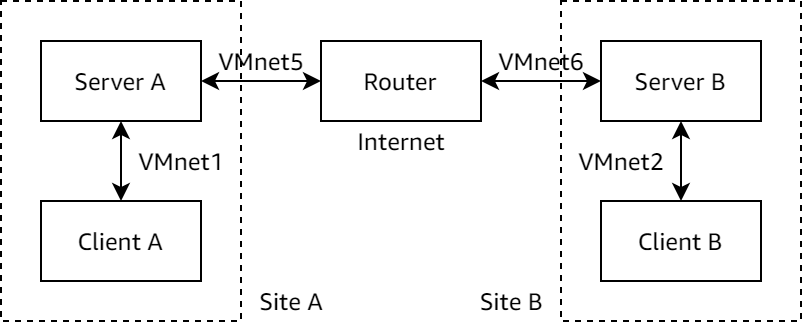
The lab is designed to work on VirtualBox platform, and the network structure is laid out as follows:
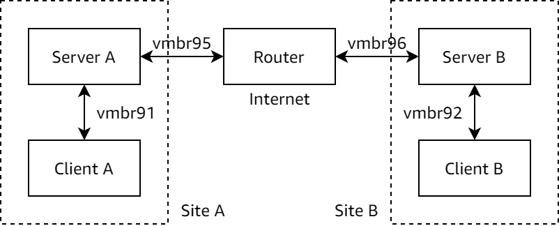
As Proxmox VE requires bridges to be named as vmbr# where # is a number, I renamed the networks as follows:
To create the networks, I edit /etc/network/interfaces to append these lines:
auto vmbr91
iface vmbr91 inet manual
    bridge_ports none
    bridge_stp off
    bridge_fd 0

auto vmbr92
iface vmbr92 inet manual
    bridge_ports none
    bridge_stp off
    bridge_fd 0

auto vmbr95
iface vmbr95 inet manual
    bridge_ports none
    bridge_stp off
    bridge_fd 0

auto vmbr96
iface vmbr96 inet manual
    bridge_ports none
    bridge_stp off
    bridge_fd 0
The bridge_stp and bridge_fd options turns off STP, which is usually a better choice in a virtualized environment.
I then bring up the new bridges so VMs can later be attached to:
ifup vmbr91 vmbr92 vmbr95 vmbr96
Now it’s time to set up the VMs.
Setting up containers
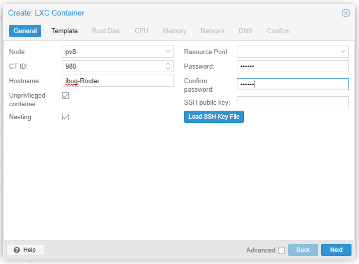
As explained above, container is an excellent replacement for full-fledged virtual machines for this lab, so I create containers using the Proxmox VE web interface.
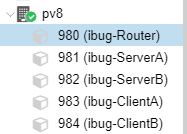
It’s also helpful to make a plan for the container IDs first, since I will heavily utilize pct enter to get into the container. The web console won’t work with some shortcut keys, notably Ctrl+W and Ctrl+T.
| Container (Name) | ID | Network | IP Address |
|---|---|---|---|
| Router | 980 | vmbr95 vmbr96 |
10.55.55.55/24 10.66.66.66/24 |
| Server A | 981 | vmbr91 vmbr95 |
192.168.1.1/24 10.55.55.1/24 Gateway 10.55.55.55 |
| Server B | 982 | vmbr92 vmbr96 |
192.168.2.1/24 10.66.66.1/24 Gateway 10.66.66.66 |
| Client A | 983 | vmbr91 | 192.168.1.2 Gateway 192.168.1.1 |
| Client B | 984 | vmbr92 | 192.168.2.2 Gateway 192.168.2.1 |
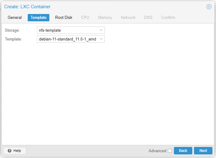
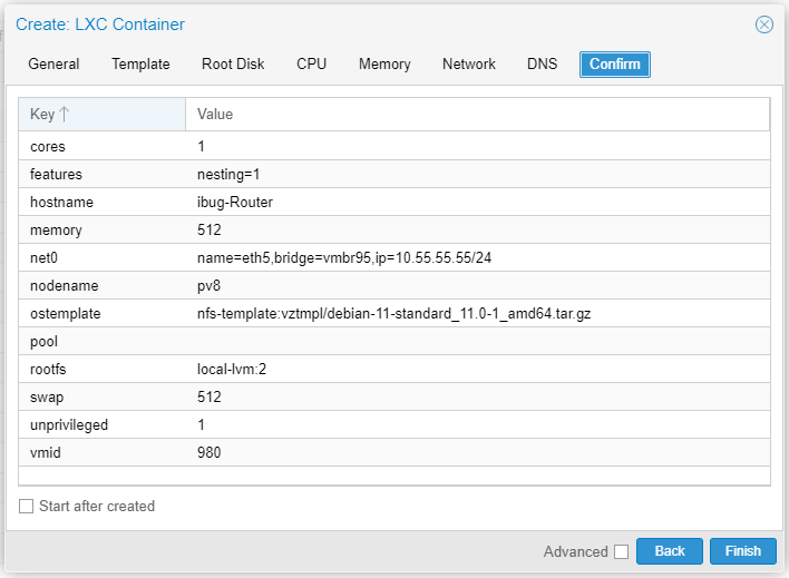
Also I’m more comfortable with newer software, so I go with the Debian 11 template provided by Proxmox.
The rest of the settings aren’t of much interest, and the default settings should suffice. On a side note, 2 GB is more than abundant for Root Disk because I need virtually no extra software to work on this lab.
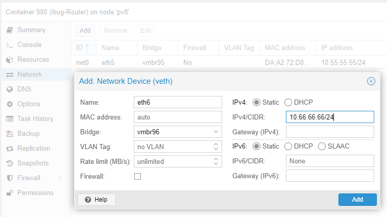
Don’t start the container right now, because there’s another network interface to be added. I head to the page to add eth6 for the router, connecting to vmbr96 as illustrated in the graph.
To save some time, I created the remaining containers using pct command. The command for creating CT 981 is as follows and the others are similar (omitted for brevity).
pct create 981 nfs-template:vztmpl/debian-11-standard_11.0-1_amd64.tar.gz \
  --rootfs local-lvm:2 \
  --hostname ibug-ServerA \
  --net0 name=eth1,bridge=vmbr91,firewall=0,ip=192.168.1.1/24 \
  --net1 name=eth5,bridge=vmbr95,firewall=0,ip=10.55.55.1/24,gw=10.55.55.55 \
  --unprivileged 1
Now that the containers have been created, it’s time to get some extra software ready for the lab.
Configure containers
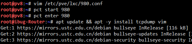
The lab originally requires capturing traffic with Wireshark on Windows Server, but on Linux it’s more typical to do this with tcpdump, which needs to be installed on the Router. Additionally to make working and debugging easier, tcpdump and a text editor of your choice should also go on the Router and the two Servers. So I install Vim and tcpdump on all three containers mentioned. No extra software is needed for the two Clients.
You may find it easier to temporarily change the network setting to allow the container to connect to the APT repository, install the software and then change it back.
But for me I’d rather “just do it”, so I connect the Router container to the external network and run apt install as needed.
And then I configure the router to perform NAT for other containers to reach the outer world, so that I can do apt install directly (iptables lines). It’s also helpful to configure the routing table so the Clients can reach each other easily (ip route lines).
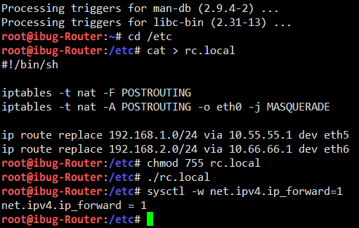
I also need to enable IP forwarding on the Router and both Servers.
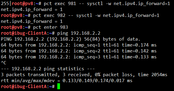
I can now see that Client A can reach Client B correctly. If I do packet capturing on the Router or either Server, I can see plaintext traffic going through.
If you can reach here, it means your lab environment is now ready as I do.
IPsec rules
Linux provides native support for IPsec via the XFRM framework, and the (primitive) tool to manage it is the ip xfrm command. The XFRM framework matches packets with policies (as Security Policies, SP) and transforms (hence the name) packets with states (as Security Associations, SA). SP and SA are managed through two subcommands, ip xfrm policy and ip xfrm state, and there’s one last subcommand ip xfrm monitor that may come in handy from time to time.
ip-xfrm command
The syntax for ip xfrm policy is as follows. Only add and delete are given because we’re not interested in others. The full syntax can always be seen via ip xfrm policy help and the man page.
ip xfrm policy add SELECTOR dir DIR tmpl TMPL [ tmpl TMPL ]...
ip xfrm policy delete SELECTOR dir DIR
ip xfrm policy flush  # deletes everything

SELECTOR := [ src IP/CIDR ] [ dst IP/CIDR ] [ dev DEV ] [ UPSPEC ]
DIR := in | out | fwd
TMPL := [ src IP ] [ dst IP ] [ proto PROTO ]
        [ spi SPI ] [ mode MODE ] [ reqid REQID ]
MODE := transport | tunnel
The syntax for ip xfrm state is as follows. Similarly, ip xfrm state help gives the full syntax.
ip xfrm state add TMPL ALGO [ ALGO ]...
ip xfrm state delete TMPL
ip xfrm state flush  # deletes everything

ALGO := { enc | auth } ALGO-NAME ALGO-KEY |
        aead ALGO-NAME ALGO-KEY ALGO-ICV-LEN
One important note
Among all the elements there’s one I’d like to specifically note: the direction dir isn’t quite the same as INPUT / OUTPUT / FORWARD as in the iptables firewall. Instead it carries the following meaning (source):
| Security Policy | Meaning |
|---|---|
| Output policy (dir out) | SP works as a selector on outgoing packets to select which are to be encrypted+encapsulated (analogous to firewall POSTROUTING chain) |
| Input policy (dir in) | SP works as a selector on incoming packets which already have been decrypted+decapsulated and have a destination IP local to the system (analogous to firewall INPUT chain) |
| Forward policy (dir fwd) | SP works as a selector on incoming packets which already have been decrypted+decapsulated and have a destination IP not local to the system (analogous to firewall FORWARD chain) |
So the direction works like this:
- The
dir outis for encryption policies - The
dir inanddir fwdis to select and filter encrypted packets
The curious may now ask: Where are the decryption policies?
The answer is: The Security Associations! (Surprise!)
Incoming IPsec packets (ESP, AH etc.) that match a SA will always be decrypted, regardless of configured SPs (so SA is analogous to the firewall PREROUTING chain). However, if the decrypted packet (or plain traffic) does not match a valid SP, it’s silently dropped and no further processing in the Linux network stack is done.
I got trapped in this part for an hour in my initial experiments because it’s just too intuitive to misunderstand how dir works. And that’s why I’m taking a special note on this.
Configure IPsec rules
Because I want to enable the Clients to connect to each other via the Servers, I configure an output policy and a forwarding policy on both Servers (with the opposite directions, of course).
I add the Security Associations on Server A with the following commands. Note that it’s often better to generate the keys randomly than using a easily guessable value.
SPI=0x69427567
AUTHKEY=0x0123456789ABCDEF0123456789ABCDEF
ENCKEY=0xFEDCBA9876543210FEDCBA9876543210

ip xfrm state add \
  src 10.55.55.1 dst 10.66.66.1 proto esp spi $SPI mode tunnel \
  auth sha256 $AUTHKEY enc aes $ENCKEY
ip xfrm state add \
  src 10.66.66.1 dst 10.55.55.1 proto esp spi $SPI mode tunnel \
  auth sha256 $AUTHKEY enc aes $ENCKEY
As the encrypted packets will be transported through the virtual “public Internet”, the source and destination addresses must be those of the public interfaces on the Servers.
You can of course use different Security Parameter Indices and keys for both directions, but I choose the same parameters for simplicity.
I then add the Security Policies on Server A with the following commands:
ip xfrm policy add \
  src 192.168.1.0/24 dst 192.168.2.0/24 dir out \
  tmpl src 10.55.55.1 dst 10.66.66.1 proto esp spi $SPI mode tunnel
ip xfrm policy add \
  src 192.168.2.0/24 dst 192.168.1.0/24 dir fwd \
  tmpl src 10.66.66.1 dst 10.55.55.1 proto esp spi $SPI mode tunnel
I also add the Security Associations on Server B with the same Security Parameter Index, Authentication Key and Encryption Key. The commands are identical to those run on Server A.
The Security Policies require minimal changes: dir out and dir fwd should be swapped on Server B. The ip xfrm policy add commands are otherwise identical.
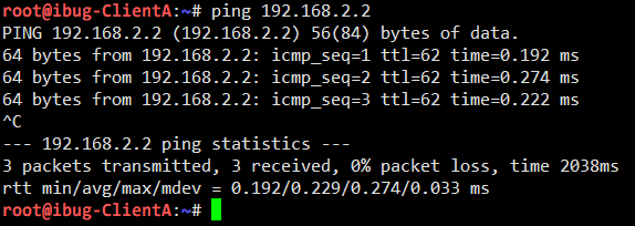
Now I enter Client A to see if Client B is still reachable:
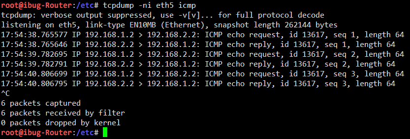
However, tcpdump on the Router shows Encrypted Security Payload instead of any plain traffic:
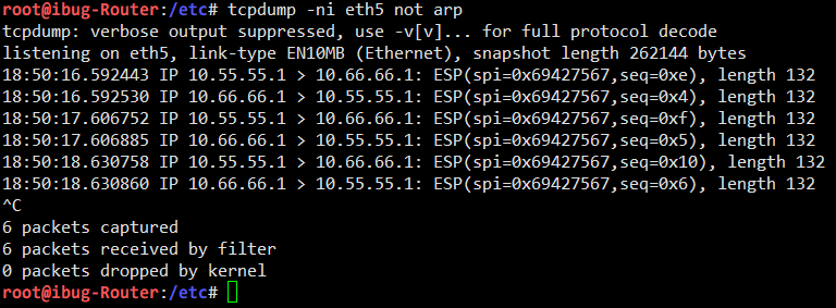
The packet capturing shows that traffic between Server A and Server B is correctly encrypted with IPsec, so that communication between the two “sites” are now secured (except the key is weak).
Inspecting traffic with Wireshark
In fact, tcpdump supports dumping captured packets to file in Pcap format, which is a universal format also supported by the popular GUI software Wireshark.
To start over again with a “clean” IPsec tunnel, I reset the Security Policies and Security Associations with
ip xfrm policy flush
ip xfrm state flush
And then I reapply all Policies and Associations with the commands shown in the previous section.
I start capturing packets to file with tcpdump:
tcpdump -ni eth5 -w a.pcap ip and not arp
I add filter expression to reduce noise (get rid of ARP and IPv6 NDP stuff), and again I send some traffic from Client A to Client B. I capture 10 packets here, which is enough for illustration purposes.
I take the Pcap file from the container to my (Windows) computer, and open it with Wireshark:
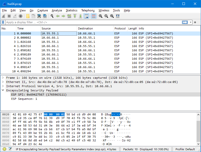
The captured packets are correct - they’re encrypted in ESP format.
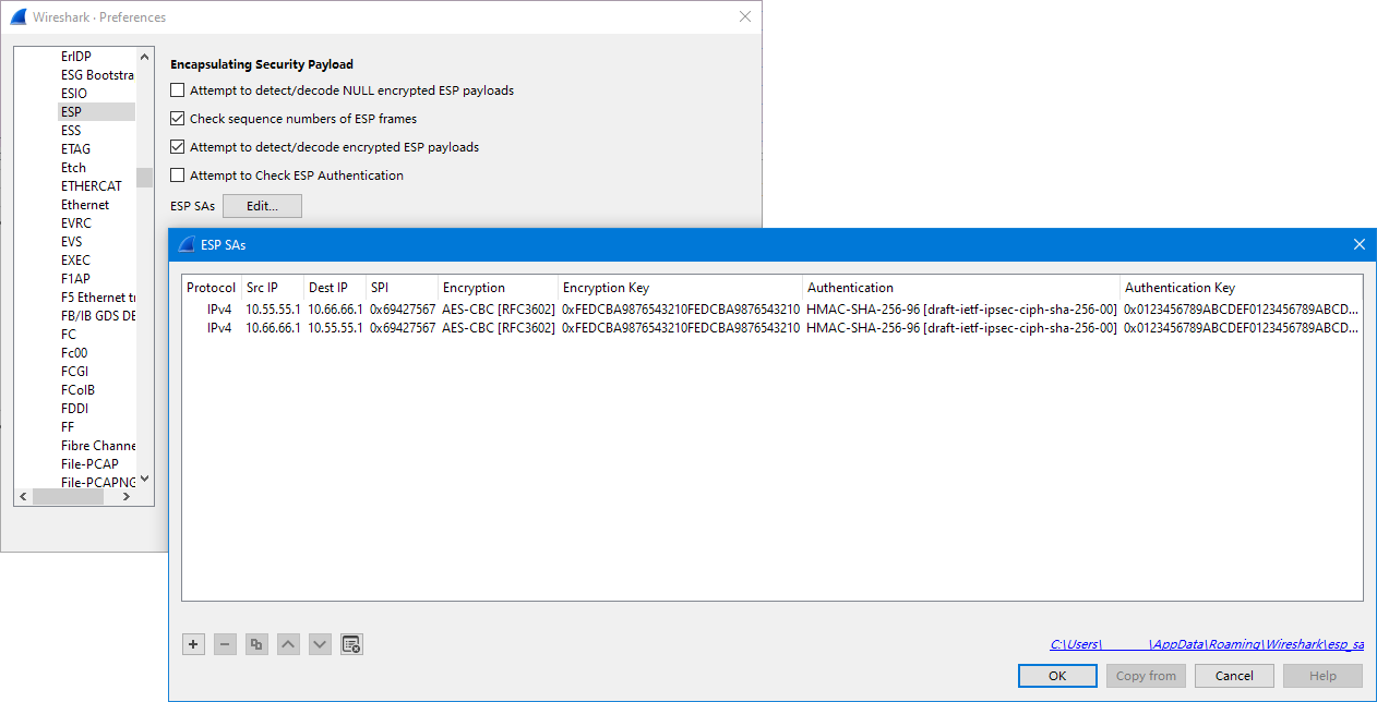
I then head to Edit → Preferences, locate Protocol » ESP on the left, and add the Security Associations used in this experiment. I also tick the “Attempt to detect/decode encrypted ESP payloads” checkbox.
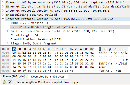
Now I go back to the main screen, and I can see that Wireshark decrypts the ESP payload using the SAs I just supplied. The inner packet data is revealed to be ICMP packets because I use Ping to perform the reachability test all the way.
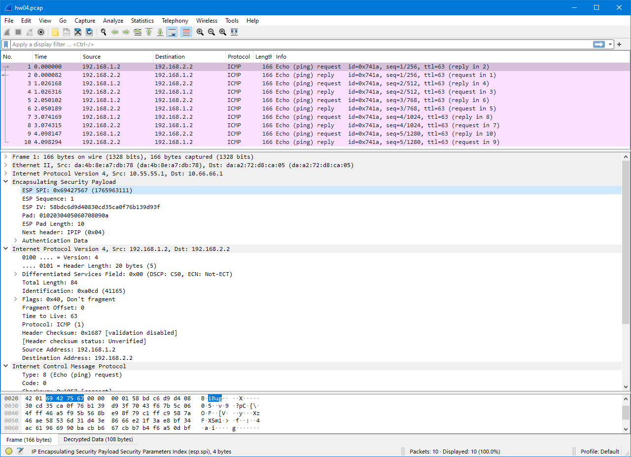
Wireshark also highlights all packets because they are identified to belong to the same “connection” (ICMP session).
If you’re wondering, the decrypted payload content (shown in the “Decrypted Data” tab at the bottom) is a complete IPv4 packet, plus ESP metadata like authentication information and a “Next Header” value. The Next Header is the same as the “Protocol” field in an ordinary IPv4 packet. For an IPv4 packet encapsulated, the Next Header value is 4, which is the same value as “IP-in-IP tunnel”. For carried IPv6 traffic, the Next Header value is 41, the value for “IP6-in-IP tunnel” (or Simple Internet Transition, SIT).
Easter egg
Before loading SAs into Wireshark, I noticed it showing an interesting note for every other packet:
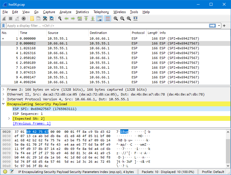
This is because Wireshark identifies streams by SPI, which is normally different for every IPsec stream, including both directions between the same pair of tunnel endpoints. When I’m using the same SPI for both directions, Wireshark gets confused and mistakes them for one stream, and suggests incrementing sequence numbers for duplicated packets.
Bonus: IPsec tunnel mode vs. IP-in-IP tunneling inside IPsec transport mode
Big shoutout to my friend @RTXUX who originally came up with this idea!
Notice how Wireshark shows the “decrypted data” as a complete IP packet, and that the “Next Header” field in the outer ESP packet is 4 (IP-in-IP tunneling protocol):
Recalling the differences between IPsec transport mode and tunnel mode as taught in class or covered by Oracle’s documentation:
- In transport mode, the IP addresses in the outer header are used to determine the IPsec policy that will be applied to the packet.
- In tunnel mode, two IP headers are sent. The inner IP packet determines the IPsec policy that protects its contents.
It’s reasonable to wonder if the tunnel mode is equivalent to the transport mode with an identical IP-in-IP tunnel inside. This wouldn’t sound too silly because with an IP-based tunneling protocol like IP-in-IP or GRE, we’re literally wrapping up the inner payload and using the tunneling protocol as a means of transport (at Transport Layer), and the Transport Layer is exactly what’s carried in an IPsec transport mode packet. The only way to find this out is with practice.
To test if they’re compatible, continuing from the end state of the course lab, I reset all Security Policies and Security Associations on Server A while leaving Server B intact.
# on Server A
ip xfrm policy flush
ip xfrm state flush
The test setup would be an IP-in-IP tunnel as it has the same protocol number (4) as the ESP payload, so I create one on Server A first.
ip tunnel add ipip0 mode ipip local 10.55.55.1 remote 10.66.66.1 ttl 64
ip link set ipip0 up
I also need to setup routing, since I don’t have IPsec policies to wrap it up for me. (Note: You can add a network address to this tunnel interface, but it’s not necessary.)
ip route add 192.168.2.0/24 dev ipip0
Then I wrap it up with the same IPsec policies, except that the mode has been switched to “transport” and there’s no longer a “forward” direction, since the transported packets are IP-in-IP packets with the two servers being the source and the destination:
ip xfrm policy add \
  src 10.55.55.1 dst 10.66.66.1 dir out \
  tmpl src 10.55.55.1 dst 10.66.66.1 proto esp spi $SPI mode transport
ip xfrm policy add \
  src 10.66.66.1 dst 10.55.55.1 dir in \
  tmpl src 10.66.66.1 dst 10.55.55.1 proto esp spi $SPI mode transport
The Security Associations need no change as the encrypted packets will have the same source, destination and SPI.
With Server B retaining its original setup, I can confirm that Client A can still reach Client B:
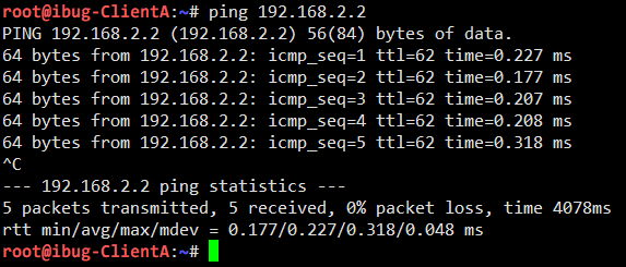
This phenomenon at least proves that IPsec tunnel mode is compatible with IP-in-IP tunnel inside IPsec transport mode.
Same as above, I perform packet capturing on the Router and compare the results in Wireshark:
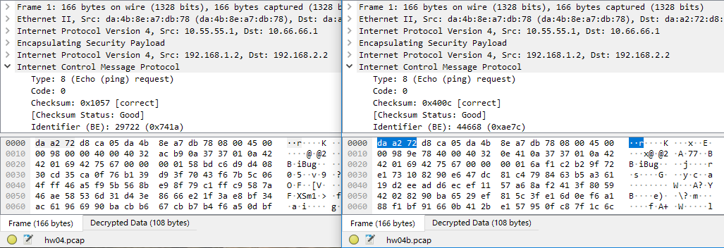
Seeing how they have identical structures, I can now draw the conclusion that the two modes are fully equivalent, if properly set up.
Caveats
I emphasized properly set up at the end of the last line above. This is because Linux implements IPsec as a policy-based VPN (and so does Windows), as opposed to route-based VPNs (with OpenVPN being a common example). There’s a difference worth noting.
-
Policy-based VPN matches and works on outgoing packets, which may have already gone through multiple levels of routing decisions, and are recaptured before they leave the network processing stack.
Wikipedia has an excellent graph showing the packet flow in Linux network stack, and you can see that “xfrm lookup” happens right before the packet processing ends.

Policy-based VPN has the advantage of minimizing the setup job, as it works as a tunnel and handles transport policies on its own, but is sometimes less convenient for being a separate facility from the already-complicated routing policies and NAT rules that a common network gateway may already have. Also, you may want to avoid multiple levels of encryption for both performance reasons and security concerns, which further adds to the complexity of your Security Policies and management efforts.
-
Route-based VPN creates a virtual network interface (usually either TUN or TAP) and applies cryptographic transformations to traffic sent to or received from this interface. It has the advantage of integrating perfectly with existing routing policies, NAT rules, firewall (if the firewall is configured on the tunnel endpoint) and even packet capturing. As route-based VPNs use the same routing policy database (RPDB) as the main network stack, you can even run dynamic routing protocols inside, like OSPF or BGP. In fact, it is a very common modus operandi in DN42 to connect with WireGuard and run BGP inside.
Depending on the software used, it may be even easier to setup a route-based VPN (like OpenVPN), but traffic filtering needs to be done from inside. This is virtually the only disadvantage of route-based VPN.
It’s often a matter of choice between these options. There are more route-based VPN implementations (OpenVPN, WireGuard etc.) but enterprise support for policy-based VPN is more mature, so a decision is to be made when it comes to deployment. I personally never used policy-based VPN outside this lab because I often need complex routing policies and NAT rules that policy VPNs are bad at, but YMMV.
Troubleshooting
Finally, if you are going to use my article as a hands-on tutorial for setting up a similar lab, some troubleshooting experiences and tips would certainly turn useful.
- Creating
ip xfrm stateresults in Protocol not supported: Check on the Proxmox VE host ifmodprobe xfrm4_tunnelworks correctly. It may fail with Unknown symbol in module or Invalid argument. In either case, update the Linux kernel package to the latest and reboot the host. - Decrypted packets not found except in
tcpdump: Check/proc/net/xfrm_statand see which number is going up. This kernel interface provides statistics for packets dropped by the XFRM framework. Refer to the kernel documentation to see what each number means. -
Bonus section:
-
ip tunnel addshowingadd tunnel "tunl0": failed: No such device: Theipipandtunnel4modules need to be loaded on the host. A simplemodprobecommand should do it
-


Leave a comment